

Industrial automation is a multi disciplinary branch of engineering, which helps to improve the productivity of the industrial processes with reduced human assistance. It is the key aspect in Industry 4.0 which is considered as the fourth industrial revolution. The scope of this branch varies from the automation of a simple light bulb to complex machines and processes. Industrial automation will replace many conventional jobs in the future. Even though it causes the replacement of many professions, it also demands the need for new skilled professionals in this field. A wide range of opportunities are waiting for the people who seek automation as their career. This blog aims to give an overview and area of specializations in Industrial process control and automation.
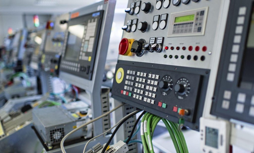
Figure 1 Human Machine interface (HMI) Panel
The usage of closed-loop control systems started after the industrial revolution. Relay-timer based systems and mechanical controls were used initially for the automation. The technology got its momentum after the improvement in microprocessors and embedded systems. It made the process control simpler and efficient. The controller is also known as the Programmable Logic Controller (PLC) is the core of process control. There can be a single PLC or a group of PLC systems to control a process depending on the complexity of the control functions required. Program is stored in the programmable logic controller in non-volatile memory. Programmable logic controllers contain a variable number of Input/output (I/O) ports and are based typically on Reduced Instruction Set Computer (RISC). PLC based Control Systems, in its simple form are ON/OFF systems, when the actuators (outputs) are made ON/OFF based on the status of sensors (inputs) and applied logic. Actuators can be motors, solenoids etc, and sensors can limit switches, proximity sensors, photo sensors etc. When analog value like, temperature, pressure, flow etc is to be controlled, the output value is measured using a transmitter and compared with the reference (set value) and based on a PID algorithm the output is given to an actuating device; which can be control valve, variable frequency drive or thyristors for heating application. In other words, a closed-loop system is a fully automatic control system in which its control actions are dependent on the output in some way.
Fire extinguishing system is a perfect example for an automated process. It is designed to monitor and protect the plant from the risk of fire. It is usually found in industries, hospitals and commercial buildings. A separate control panel is assigned to control all components which are related to the fire safety system. The system consists of PLC, fire detectors, sirens etc. The whole process is controlled by a programmable logic controller (PLC). The fire extinguishing system can detect the fire, discharge the water or gas into the flames and alert using a siren or alarm in the case of a fire hazard. The completely automated fire extinguishing system does not need human assistance to ensure the protection.
Automation Engineers are the people who design, implement and maintain different aspects in automation projects. The Industrial Automation Engineers can be classified broadly into two types, Software Automation Engineers and Electrical Automation Engineers. The software automation engineers are responsible for developing the software applications related to automation. Since I am working as an electrical automation engineer, I will be explaining about process control automation in this blog. Electrical automation engineers design the control systems to automate the whole industrial process. The manufacturing processes range from manufacturing processes of food materials to manufacturing automobiles.

Figure 2 S7-1500 Programmable Logic Controller (PLC)
The process control automation engineers create an automation design after analyzing the Piping and Instrumentation Diagram (P&ID), which is a detailed diagram representing process equipment and control devices. The automation design includes software and hardware designs. The hardware design includes the selection of various components that facilitates process control, electrical documentation, cable specification selection. There are certain rules and standards that must be followed when an automation system is designed. IEC 61499 is one among them. IEC 61499 which was published by International Electro technical Commission in 2005 provides standards about industrial automation and distributed control systems.It is the Standard for the development, reuse and deployment of Function Blocks in distributed and embedded industrial control and automation systems. The standard consists of three parts as the architecture for distributed systems (IEC 61499-1), Software tool requirements (IEC 61499-2) and Rules for compliance profiles (IEC 61499-4) (IEC 61499-3 was withdrawn in 2008). The standard provides the details about the modern automation systems and real time control.
The hardware design components can be classified mainly into two categories: Panel components and Field components. Panel components include Power Supply Modules, Busbars, meters such as Ammeters, Voltmeters, Energy meters, Cooling and Lighting systems inside the control panel, Communication Modules for Actuator-Sensor Interface, PROFINET and PROFIBUS, PLC, Modem, Line Filters, protective devices in the control panel such as MCCB, Thermal-magnetic and electronic MCB, RCD, Surge diverter (LA/SD), HRC Fuse, different drives such as Variable Frequency Drive (VFD) for Induction Motors (IM), Servo Motor Control Drive, Thyristor Power Controller for heating loads. Field components include Sensors and Transducers located in the field for monitoring different process parameters like Pressure, Temperature, Flow, Density etc. The specifications such as type, make, series and rating of each component should be specified by the automation engineer. Each component in the field and panel are labelled with a unique name called tag which specifies its type and is very helpful during maintenance.
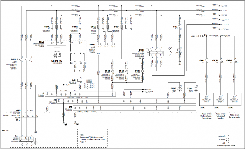
Figure 3 Automation Wiring Diagram
Electrical documentation includes the arrangement and wiring diagram of the electrical control panel. Different revisions may be made during documentation by the engineer. The modifications performed in each revision are listed separately in the document. Revisions are made even after the practical implementation of the hardware components after the FAT. The document version after the FAT is known as-built drawing. The document will be revised based on new changes in the automation designs. The automation designers strictly follow the standards such as IEC, IEEE, NEMA etc. So, the in-depth knowledge in standards is required for automation engineers. The Electrical automation drawings are made usually in the CAD software such as Eplan Electric P8, SEE Electrical V8R2, PC Schematic Automation etc.
Software design involves the program and interface based on the requirements. The program is usually programmed using Ladder Diagram (LD) programming language, which can be simulated before downloading into the programmable logic controllers (PLCs). Sequential Function Charts (SFC), Function Block Diagram (FBD), Structured Text (ST) and Instruction List (IL) are some of the programming languages. The program is downloaded to PLC before the Factory Acceptance Test (FAT).
The recent advancements in SCADA and DCS have enabled their integration to automation technology. The Supervisory control and data acquisition system uses the real-time data to monitor and control the processes. SCADA systems were first used in the 1960s in telecommunication engineering applications. SCADA is a computer-based system which can be applied in a large range of applications such as process control, substation automation, distribution system automation and many more.

Figure 4 SCADA system layout
SCADA uses computers, networked data communications and graphical Human Machine Interfaces (HMIs) to enable a high-level process supervisory management and control. As its name indicates, the Distributed Control System (DCS) is distributed throughout the system. Instead of a centralized system, it uses distributed controllers performing unique tasks at remote locations to control the processes. A DCS typically uses custom-designed processors as controllers and uses both proprietary interconnections and Communications protocols for communication. Apart from these technologies, the technologies like artificial intelligence (AI), Machine learning (ML), Internet of things (IoT), Blockchain and Big data are used in modern automation systems.

Figure 5 Supervisory Control And Data Acquisition (SCADA) Control Room
The person who wishes to pursue a career in Automation Engineering should need a wide range of knowledge in different subjects of electrical engineering. The familiarity in different subjects such as Control Systems, Power Systems, Instrumentation, Electrical Machines, Electrical Drives, Safety Related Control System, Computer Science and Engineering is required to be a successful Automation Engineer.
I guess you guys are interested in knowing more about this topic, its scope and future opportunities in this sector. In that case, for further information and research, refer to the given references:
1. Curtis D Johnson,” Process Control Instrumentation Technology”, PHI, 1986
2. A Course in Electrical and Electronic Measurements and Instrumentation, A. K. Sawhney
3. Sensors and Actuators: Engineering System Instrumentation, Second Edition 2nd Edition, Clarence W. de Silva
4. Practical Process Control for. Engineers and Technicians, Wolfgang Altmann
5. http://www.output-automation.dk/
6. http://drawout.dk/
7. https://www.emerson.com/en-in
8. https://www.rockwellautomation.com/
9. https://www.honeywellprocess.com/en-US/pages/default.aspx
10.https://www.mitsubishielectric.in/
11. https://www.ia.omron.com/
About author
Er. Sanjo Sibi Moolamkunnam graduated in Electrical and Electronics Engineering (EEE) from St. Joseph’s College of Engineering and Technology, Pala (APJAKTU). Currently, he is an Electrical Automation Engineer at Drawout ApS, Aalborg, Denmark. He started his career as a visiting lecturer in St. Mary’s Industrial Training Institute (ITI), Pulincunnoo, Alappuzha, Kerala. He is an active member of IEEE PES and Member of R&D committee, IEEE Smart Grids, USA.
His current research interests include power systems protection, power systems faults and outages, digital substations, distribution system automation, HVDC transmission, FACTS, Microgrid operation and control, DC microgrids, Power quality, distributed generation, smart grids, solid-state circuit breakers and protective devices, power systems reliability and resiliency, Grid Integration of EVs, Power system instrumentation, automation and control, SCADA etc.
Mail: sanjosibim@gmail.com
Website: https://sites.google.com/view/sanjo-sibi
LinkedIn: https://www.linkedin.com/in/sanjo-sibi-moolamkunnam-151490134


Such a good information
Very informative and awesome writing